
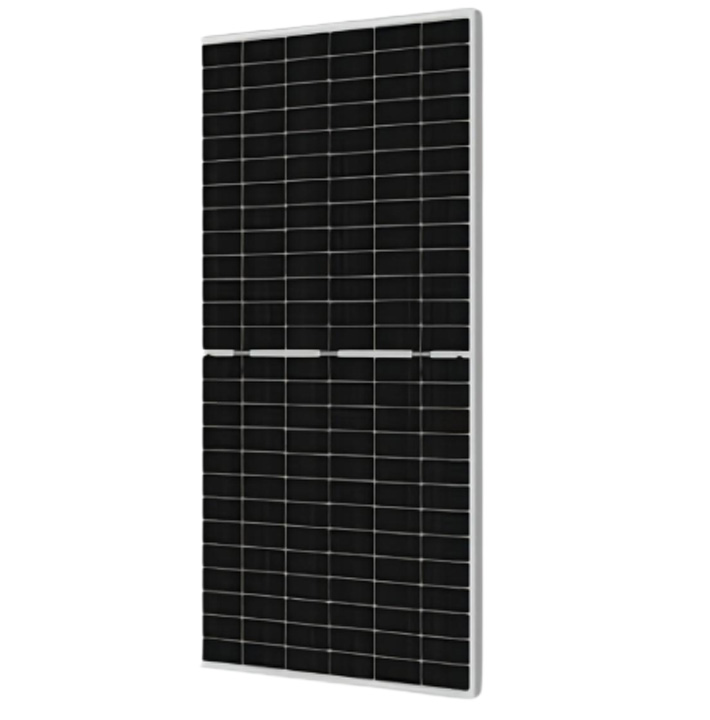
0BB (busbar-free technology) is an innovation in the field of photovoltaic cells, which aims to optimize the electrode design of traditional solar cells. Traditional cells usually use busbars (thick wires) and sub-grids (thin wires) to collect current, while 0BB technology completely removes the busbar and only retains a denser sub-grid structure, thereby reducing resistance loss and shading area.
Core advantages
Higher conversion efficiency: Removing the busbar can reduce shading on the cell surface and increase the effective light-receiving area; at the same time, it reduces resistance loss and improves current output efficiency.
Lower silver paste consumption: The busbar usually requires a large amount of silver paste. 0BB technology can reduce the use of silver paste by about 30%, significantly reducing material costs (silver paste accounts for about 10-15% of the cell cost).
Better reliability: Fewer welding points, reducing the risk of cell cracking, and improving the long-term stability of components.
Strong compatibility: 0BB can be combined with other high-efficiency technologies (such as heterojunction HJT, TOPCon, BC) to further amplify the technical advantages.
Two 0BB technology process flows
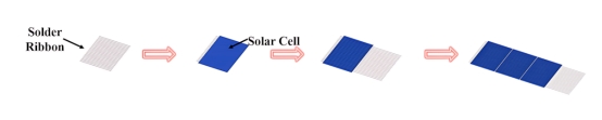
Production process of welding type 0BB technology Welding type
0BB: high temperature (230°C) short time (<2 seconds) welding to form a welding strip in contact with the solar.
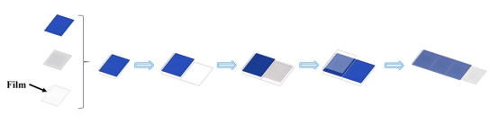
Production process of integrated film cover (IFC) 0BB technology
IFC 0BB: Use a carrier film (pre-cured film) to press the solder tape at low temperature (140–150°C) and form an ohmic contact through lamination.
Main materials of the two 0BB technologies
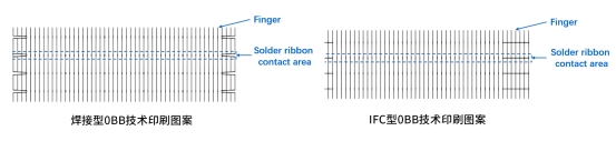
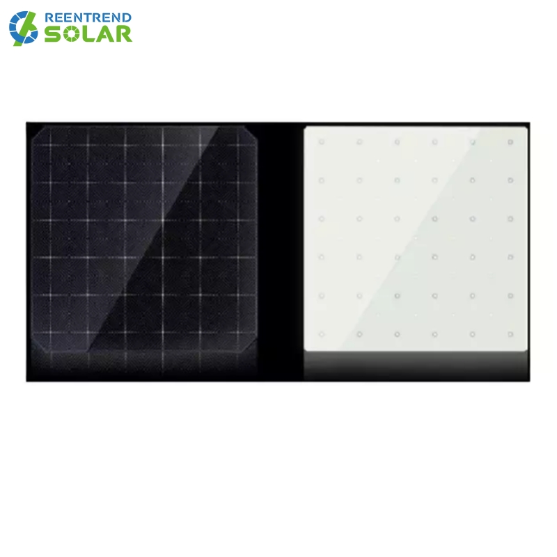
Cell design: Both 0BB cell designs are designed to reduce the use of silver while maintaining efficient power output. IFC technology shows greater advantages in silver consumption.
Soldering tape material: The selection of low melting point solder is critical to the welding process and component performance. The melting point and composition of different solders will affect the alloying reaction between the welding tape and the cell.
Packaging material: The design of the packaging structure and the selection of materials directly affect the optical performance and durability of the component. IFC technology achieves low temperature welding through an additional carrier film layer, reducing the risk of thermal damage.
Electrical performance analysis
Contact resistance
Results and analysis of contact resistance tests of two 0BB technologies
Test purpose: Contact resistance directly affects the series resistance (Rs) and power loss of photovoltaic modules. Lower contact resistance means higher module efficiency.
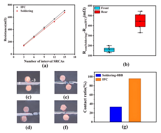
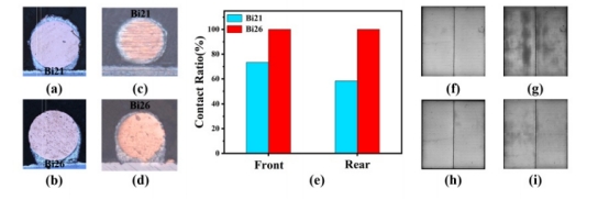
Test method: Use a probe to measure the resistance between the welding ribbon and the finger electrodes of the cell. The resistance of the finger electrodes (Rfig) is calculated by linear fitting, and the contact resistance (Rcon) is calculated in combination with the formula. Test results:
IFC technology: The contact resistance (Rcon) is lower, with an average value of 161 mΩ (front) and 444 mΩ (back) lower than that of welding technology.
Welding technology: The contact resistance is higher, mainly because it relies only on fixed pressure during welding, which may lead to incomplete contact.
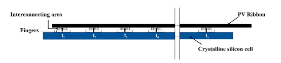
Schematic diagram of the contact resistance between the solder ribbon and the solar cell
The impact of contact resistance on component power loss is evaluated through theoretical calculation, the calculation formula is:
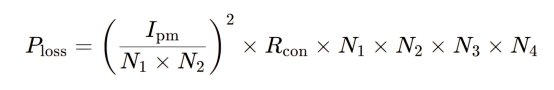
The difference in contact resistance between IFC technology and welding technology resulted in a power loss difference (ΔPloss) of 2.89 W. The difference in fill factor (FF) (ΔFF) was 0.33%.
Component power test
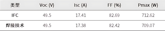
The module power (Pmax) of IFC technology is 3.55 W higher than that of welding technology, mainly due to lower contact resistance and higher fill factor (FF).
The open circuit voltage (Voc) of both technologies is the same, but the short circuit current (Isc) of IFC technology is slightly higher by 0.03 A, which may be due to the cell design of IFC technology reducing the shadow of metallization pattern and improving optical utilization.
Solder selection
Select solder suitable for both 0BB technologies to ensure the mechanical strength and electrical contact quality of the solder joint. The reliability of the solder joint directly affects the long-term stability of the module, especially in complex outdoor environments.
Test methods:
Peel test: By peeling the solder tape, measure the adhesion strength between it and the cell.
Thermal cycle test: Simulate the stability of the module under temperature change conditions.
Metallographic analysis: Observe the microstructure of the solder joint and evaluate the quality of metallurgical bonding.
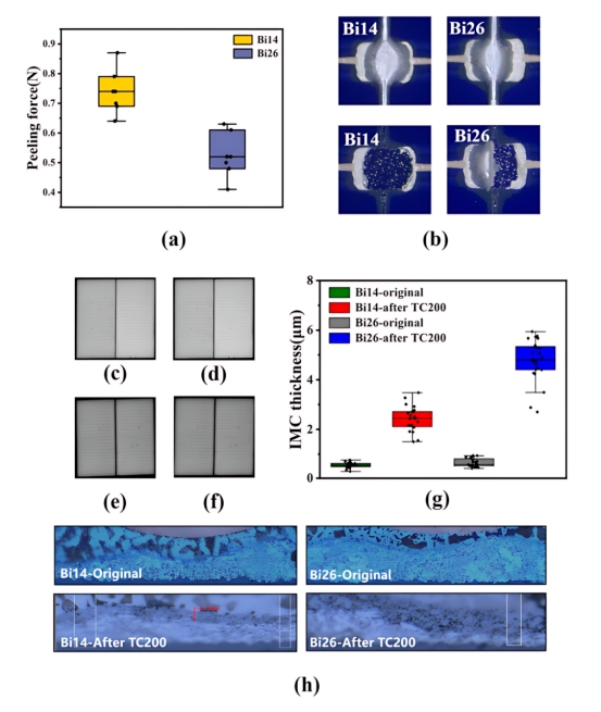
Test performance of different solders in soldering type 0BB technology
Soldering technology: Bi14 solder was selected, and its peeling force was 0.74 N, which was higher than 0.52 N of Bi26 solder. Bi14 solder showed more stable performance in thermal cycle test, and its IMC (intermetallic compound) layer thickness was 2.43 μm, which was within the recommended range (1-3 μm).
Test performance of different solders in IFC type 0BB technology
IFC technology: Bi26 solder is selected, which can better form metallurgical bonds with the solar cells during low-temperature lamination. Bi26 solder performs well in high-temperature stability tests, and no obvious desoldering occurs even in a baking test at 180°C.
Reliability test analysis
Hot spot test
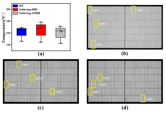
Hot spot temperature distribution and electroluminescence (EL) images
Hot spot test is an important means to evaluate the thermal stability and electrical performance of photovoltaic modules under partial shading conditions. The results show that the modules of the three technologies meet the requirements of IEC standards and have good reliability.
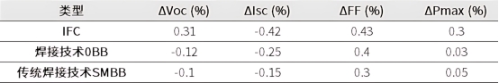
IFC technology: After the hot spot test, it shows slightly better performance than welding technology and traditional SMBB technology, especially in open circuit voltage and maximum output power.
Welding technology and traditional SMBB technology: Although it shows a small performance change after the hot spot test, the overall stability is comparable to that of IFC technology.
Thermal dynamic mechanical load testing
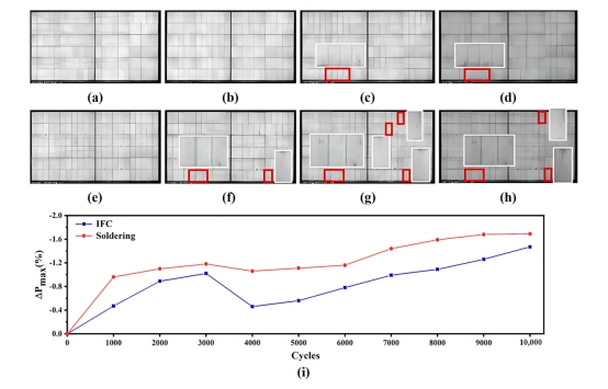
EL images during thermal dynamic mechanical load testing
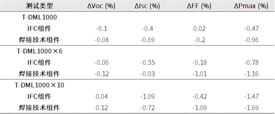
IFC component: The power loss after 10 cycles was 1.47%, showing good durability under high temperature and dynamic mechanical loads. Although some defects appeared after multiple cycle tests, the overall structure remained relatively intact.
Welding technology component: The power loss after 10 cycles was 1.69%, and more serious finger electrode fractures occurred after multiple cycles, resulting in greater power loss, indicating that it has poor stability under high temperature and dynamic mechanical loads.
Hot static mechanical load test
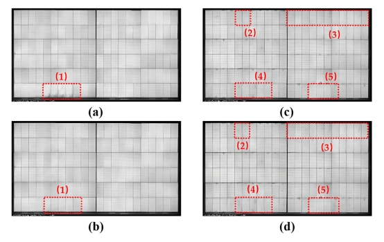
EL images during thermal static mechanical load testing
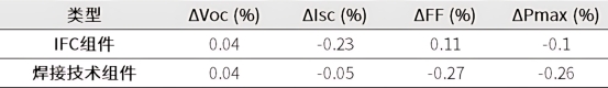
IFC technology shows better stability and durability under high temperature and static mechanical load conditions, while welding technology components show a certain performance degradation under the same conditions.
Two zero main grid (0BB) technologies - welding type and IFC type 0BB technology. Through comparative analysis, IFC technology shows lower contact resistance and higher power output, while its low-temperature lamination process effectively avoids high temperature damage to solar cells. Both types of technology components have passed rigorous tests such as thermal cycling, damp heat, hot spots and mechanical loads, verifying their reliability in long-term use.
In the future, with the continuous development of photovoltaic technology, 0BB technology is expected to play a greater role in large-scale production. By optimizing processes and materials, 0BB technology will provide important support for the photovoltaic industry to achieve higher efficiency and lower costs, and help the global clean energy transformation and sustainable development.


 English
 español
 한국의
한국의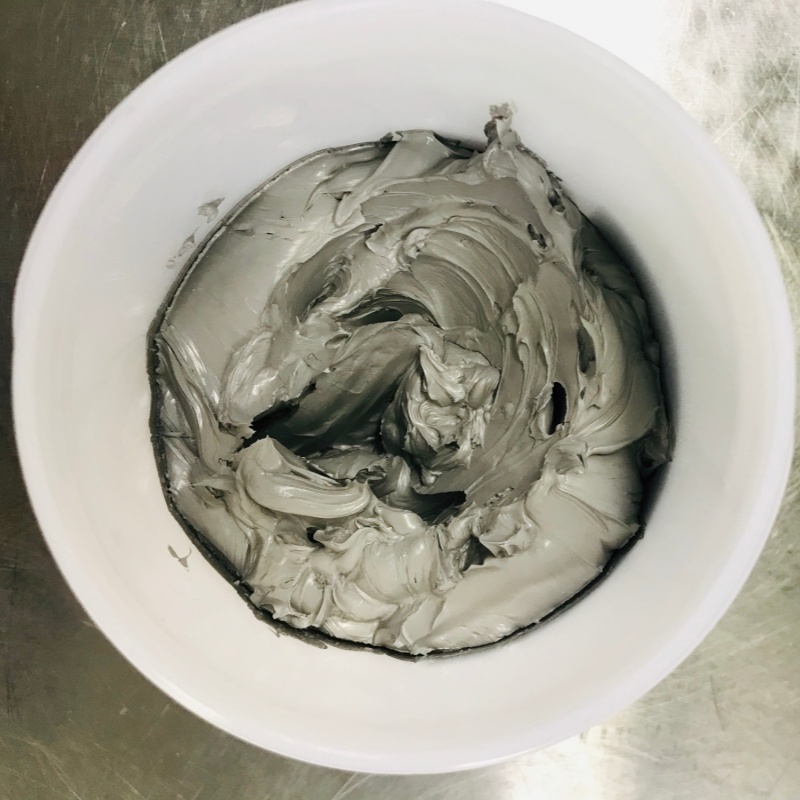


 IPv6 network supported